В първа част от уроците за зъбни колела ви показахме основите на системите от зъбни колела. Сега ще разгледаме системи от зъбни колела с повече от две колела и каскадни зъбни предавки.
- #65
- 21 Dec 2014
- 7:20
В първата част на туториала добавям ЛЕГО зъбно колело между входното и изходното колело. След изчисляване на предавката разбираме, че няма значение колко колела има между входното и изходното - отношението е само между входното и изходното.
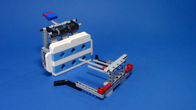
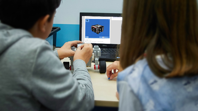
Това, обаче, не означава, че не можем да направим предавки по-големи от 5:1. Ако искате да достигнете по-високи отношения, ви трябва каскадна зъбна предавка, предавка в която имате повече от едно зъбно колело на една ос. В такива случаи отношението между колелата се умножава. За да тествам това, използвам зъбна предавка от четири колела. Свързвам един мотор към входното зъбно колело и един към изходното. След това пускам първият мотор да се движи напред и използвайки Експеримент в ЛЕГО EV3 Софтуера, разбирам колко ротации се правят от вторият мотор. Като разделим това число и броят ротации направени от първият мотор, разбираме отношението на зъбната предавка.
Можете да намерите инструкции за строене на зъбната предавка, заедно с ЛЕГО EV3 Големите мотори под "Материали".
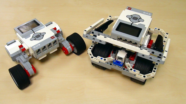
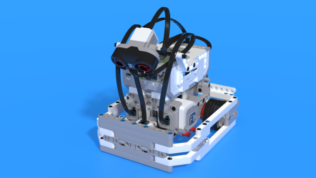
LEGO Gear Demonstration model
These are building instructions for a LEGO Mindstorms EV3 demonstration model. In the tutorial, we are using it to demonstrate the working and relations of LEGO Gears.

![]()

English
In episode 54 I introduced you to the basic concepts of gear systems. Today I will build on that knowledge. In part 1 we took a look at a gear system consisting of two gears only. But sometimes only two gears are not enough. Stay with me for the next several minutes when I'll answer the question what if we could not achieve what we need to with only two gears.
Do you remember this gear system? Now I wonder what would happen if I introduce one more gear between the driver and the follower gear. Let's calculate. So, for one rotation of the driver gear 40 teeth will go through the point of engage and that means that the grey gear will make 40 divided by 24 rotations. For each rotation of the grey gear that has 24 teeth the blue gear will make three rotations. So, for one rotation of the driver gear the follower gear will make 40 divided by 24, multiplied by 3, or 5 rotations. The same as the previous gear system. Actually, it does not matter if I put one or many gears in between. The ratio will be the same. But one thing will change. Each gear will change the direction of the rotation. So, for instance, if you need the driver and the follower gear to rotate in the same direction, you will need to put a gear in between. We will call the grey gear idler because it does not change the ratio. Now, let's see what the downside of using many gears is. I have five gears here that are attached to one another. I have blocked the big one using these two axles and, as you can see, it can't move. Still, the other big one, on the other end of the system, can move although it's attached to the first one. This is due to the gaps between the teeth of the gear wheels and this error occurs in every gear system. That's why it's better to use as few gears as possible. To illustrate that, I'll remove the gears in the middle and I'll move this gear next to the first one. Again, this one is blocked and can't move. As you can see, this one is moving way less than it did in the first construction. This error may cause you problems which is why you should try to use as few gears as possible. So far we've seen it does not matter how many gears we use. The ratio is the same as the ratio between the driver and the follower gear. Does this mean we could not achieve a ratio greater than 5? Actually, not. Let's take a look at this gear system. This time, instead of calculating the ratio, we'll use these two motors. One will drive the gear system and second one will be directly attached to the follower gear. We will find the ratio of the gear system by dividing the rotations of the driver motor by the rotations of the follower motor. Let's see how we'll do this. I have started the Lego Mindstorms EV3 software and opened a new project. But this time, instead of New Program, I'll open New Experiment. Here I have attached a brick with two motors - motors A and B. I will detect how many rotations each of the motors makes. The driver motor will be in green and the follower motor will be in red. I want motor B to move forward.
So, motor B will move forward at 100% power for 15 rotations. I will run the program on the brick.
Here you see the rotations each of the motor makes in real time. Now I'll use this tool - Analysis. I'll select point Analysis and I'll move the point till the end. As you see, motor B has made 15 rotations as it was programmed. And motor A has made minus 1 rotations. This is due to the fact that gears change the direction but the conclusion we could draw is that the gear system has a ratio of 15 to 1. So, let's get back to the gear system and see whether this is true and logical. We have three axles in this gear system. Let's calculate the number of rotations each of the axles makes. If this axle makes 1 rotation, the second one will make 5 rotations because the ratio between the red and the green gear is 1:5. If this axle makes 1 rotation, the third axle will make 3 rotations because the ratio between the yellow and the blue gear is 1:3. If the first axle makes 1 rotation, the second one will make 5 and for each rotation of the second axle the third one will make 3. Or, 5 multiplied by 3 is 15 rotations made by the third axle. It is true that the ratio of this gear system is 1:15. In conclusion, if you have gears attached to one another, without having two gears on one axle, the ratio is just the ratio between the driver and the follower gear. But if you have gears attached to one axle, the gear ratios multiply. I will stop here with the second part of the tutorials on gear systems. If you have any questions or suggestions that might be included in the next tutorial, post them as a comment below this video.
Курсове и занятия включващи този Урок
Този Урок е използван в следните курсове и занятия.
EV3 Basic Course. Introduction to robot programming, construction and sensor use
This course is designed for students, mentors and teachers that are completely new to LEGO Mindstorms EV3 robots and would like to start using them to learn, in classes or at competitions. It is quite different from previously built resources at FLLCasts because it makes no assumption on any previous knowledge and tries to introduce everything step-by-step.
- 38
- 193:26
- 30

LEGO Gears. Theory, how to and basic usage
Зъбните колела могат да бъдат силен инструмент в ръцета на този, който знае как да ги използва. В този материал ще се запознаем с основни определения и понятия , свързани със зъбните колела.
- 2
- 0
- 4
- 3d_rotation 3
FIRST LEGO League Competition. Attachments
This course is a collection of materials for many of the attachments that we've built at FLLCasts before introducing courses. The videos were built as separate different attachments for different competitions and with the following course, we try to give it a structure.
- 60
- 347:26
- 0

How to on Attachments with Gears
Зъбните колела могат да бъдат силен инструмент в ръцета на този, който знае как да ги използва. В този материал ще се запознаем с основни определения и понятия , свързани със зъбните колела.
- 6
- 0
- 0
- 3d_rotation 8
A robot a "day" keeps the questions awake. Version 1
"How to use the LEGO robots to facilitate the learning of robotics by my student at home" or simply put - "what to build now?"
After enrolling in this course we will send you a few (1-2-3) emails each month with a title "A robot a 'day'". Each email contains a robot building instructions and/or video tutorials and/or tasks that should be accomplished. After a task is accomplished we might sometimes ask for a video or picture.
This process gives a structure of the learning process where you can learn from the content. The student participates in a course, but from home and on the schedule that you decide.
- 26
- 98:39
- 47
MotoCar Bot. Work with gears and levers. Two magic tricks at once. Robot 5
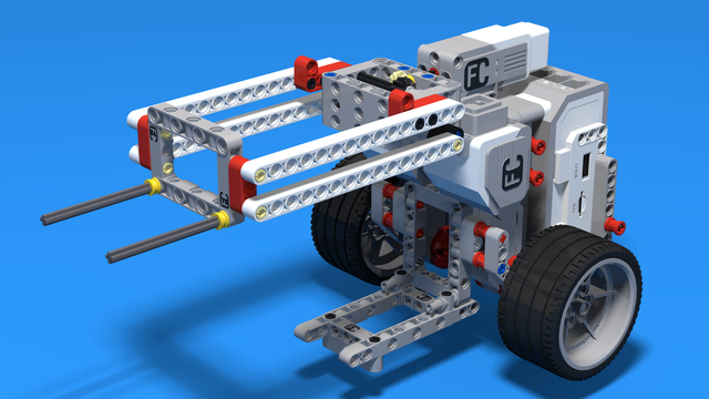
„Как да построим виличен повдигач, като използваме само зъбни колела и лостове без рейка“… Добре, трябва да признаем, че това е труден въпрос. Дори звучи трудно. Затова нека започнем с нещо лесно. Един ЛЕГО Mindstorms EV3 робот. Той повдига обекти във въздуха. Използва две зъбни колела, които работят заедно и се движат в различни посоки, като са перпендикулярни едно на друго… Това изречение започна отново да звучи трудно… Нека опитаме отново.
Следвайте инструкциите с тези 70+ стъпки и ще получите чудесен робот, като заедно с това ще научите лесен трик за използване на зъбни колела и промяна на посоката, в която те се въртят.
- 8
- 0
- 3
- 3d_rotation 1
Instructors Remote Training
If you are working with students and you want to introduce Robotics to your class or you want to mentor a FLL team, but you are insecure about your technical knowledge in the Robotics field, then this is the right place for you. Having in mind teachers' busy schedule, we have design two different schedules and added an option to design one just for you. FLLCasts's Mindstorms EV3 Robotics Online Training is the perfect match for any teacher.
After the completion of each task the participant has to upload his solution for verification.
- 136
- 280:11
- 156
Mechanics
Зъбните колела могат да бъдат силен инструмент в ръцета на този, който знае как да ги използва. В този материал ще се запознаем с основни определения и понятия , свързани със зъбните колела.
- 6
- 0
- 7
- 3d_rotation 0
Роботика с LEGO - Ниво 4.5 Време за игра
Осмото ниво от учебната програма по LEGO роботика за ученици от пети до дванадесети клас.
С помощта на роботи създадени за игри между учениците се упражнява работа с променливи. Роботите пазят натрупаните точки от играчите и правят пресмятания с информацията в променливите. Постоянно се използват познатите вече собствени блокове за групиране на функционалност. Въвежда се понятието поведение и програмите на роботите са организирани в множество нишки, които си обменят информация. В края на нивото роботите генерират задачи с числа, чрез които учениците трябва да съставят уравнение.
- 35
- 13:40
- 221

Занятие 2 - Дърпане на въже със зъбни колела
Въведение
В това занятие отново ще правим дърпане на въже, но този път ще бъде доста по традиционно!
Хареса ли ви дърпането на въже в миналото занятие? Как бихте го подобрили?

Вече се разбрахме, че не харесваме да се въргаляме по земята, след като сме паднали по време на игра на дърпане на въже. За щастие, ние можем да направим роботи, които да вършат тази работа вместо нас! Това ще направим сега, робот, който да дърпа други роботи и по възможност да ги издърпва.
- 3
- 4
- 22
- 3d_rotation 0